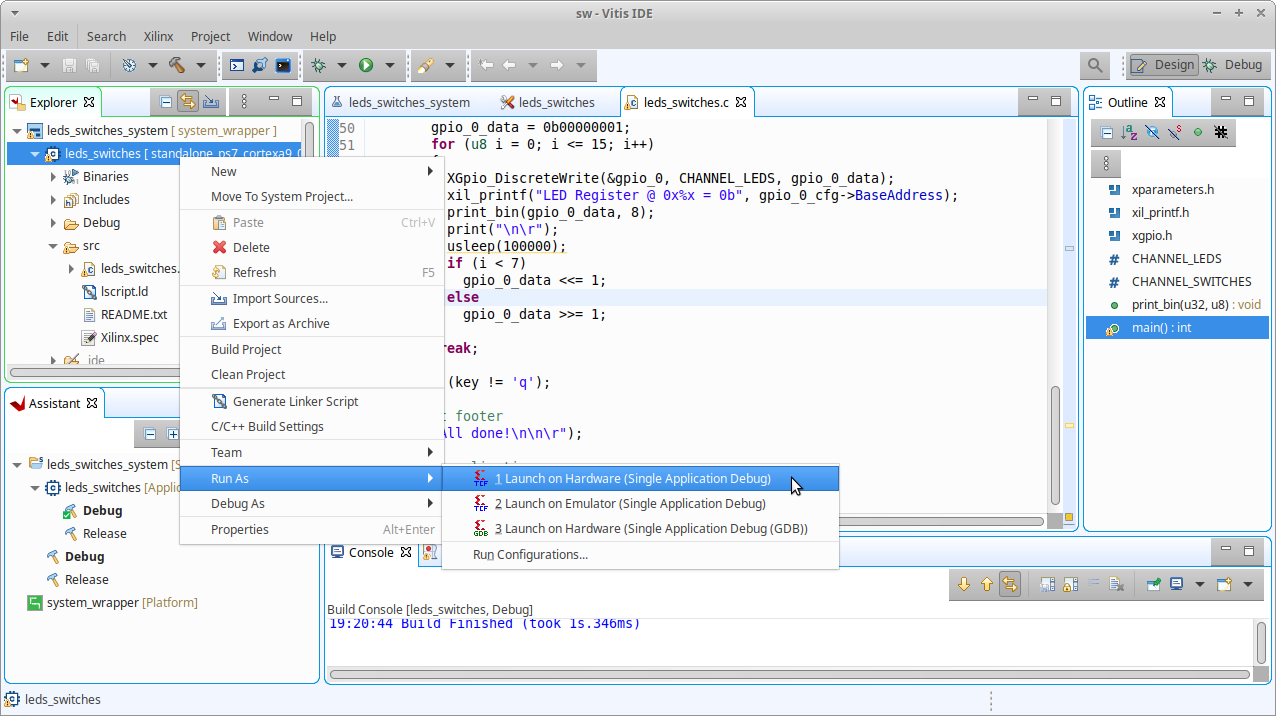
To program the PL & PS part of the Zynq-7000 FPGA right click on
leds_switches under
leds_switches_system inside the
Explorer tab and select
Run As »
Launch on Hardware (Single Application Debug) from the menu. The blue done LED will illuminate once the Programmable Logic (PL) has been programmed, the two middle LED's will then illuminate and after this the software will run on the Processor System (PS).
All being well the Minicom terminal emulator will display the following output from the application.
LED & Switch Example
Select required operation :-
r - Read from switch register
w - Write to LED register
q - Quit application
Pressing the 'r' key reads the register linked to the eight slide switches. With switches 0, 1, 4 & 5 in the 'on' position and 2, 3, 6 & 7 in the 'off' position the register read will return the following.
Switch Register @ 0x41200000 = 0b00110011
Pressing the 'w' key lights the eight LED's in sequence from right to left and then left to right, displaying the values written to the register.
LED Register @ 0x41200000 = 0b00000001
LED Register @ 0x41200000 = 0b00000010
LED Register @ 0x41200000 = 0b00000100
LED Register @ 0x41200000 = 0b00001000
LED Register @ 0x41200000 = 0b00010000
LED Register @ 0x41200000 = 0b00100000
LED Register @ 0x41200000 = 0b01000000
LED Register @ 0x41200000 = 0b10000000
LED Register @ 0x41200000 = 0b01000000
LED Register @ 0x41200000 = 0b00100000
LED Register @ 0x41200000 = 0b00010000
LED Register @ 0x41200000 = 0b00001000
LED Register @ 0x41200000 = 0b00000100
LED Register @ 0x41200000 = 0b00000010
LED Register @ 0x41200000 = 0b00000001
LED Register @ 0x41200000 = 0b00000000
Pressing the 'q' key exits the application by exiting the
main function.


 Set the boot mode jumpers on the Zedboard for JTAG.
